.
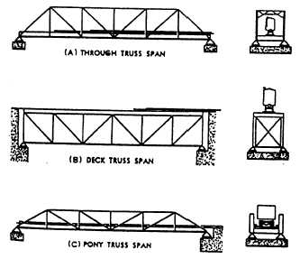
Figure 1-44.—Types of bridge spans.
Bridges
Figure 1-43.—Truss bridge.
Figure 1-43 shows the structural framework of a
single-span truss bridge. As with all bridges, the floor
and traffic loads of the truss bridge are carried by the
stringers. In the truss bridge, however, the stringers are
supported by transverse beams rather than by the bridge
abutments (and intermediate supports when needed). As
seen in the figure, these transverse beams are supported
by the structural framework of the two trusses. Finally,
the entire bridge structure plus any traffic loads are
transmitted through the end pedestals and bearing
plates to the supporting abutments. As you will note, the
nomenclature of the truss members is the same as
discussed in the preceding section; however, the
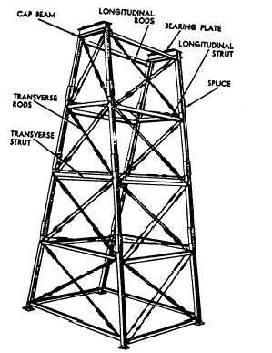
Figure 1-45.—A trestle tower.
diagonal end members, adjacent to the abutments, are
normally called end posts.
The truss framework and the manner in which the
trusses are used may differ depending upon the design
of the truss bridge. Figure 1-44 shows three examples.
View A shows a through truss span. In it, the traverse
beams are connected to the bottom chord of the trusses,
and the top chords are braced by a lateral bracing system
under which traffic passes. In the deck truss span, view
B, the traverse beams are carried by the top chord
1-22


