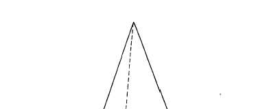
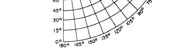
Figure 9-20.-Conic projection.
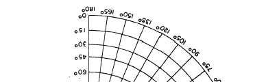
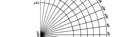
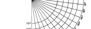
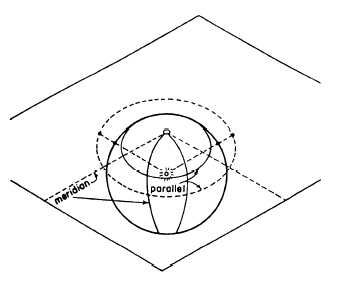
Figure 9-21.—Appearance of meridians and parallels on a
conic projection.
9-19
indicate that the map covers parts of both. Note, too,
that the direction of grid north (that is, the direction
of the north-south grid lines in the map) varies from
that of true north by O“39’E and from the magnetic
north by l“15’W.
CONIC PROJECTION
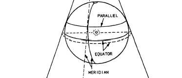
To grasp the concept of conic projection, again
imagine the earth as a glass sphere with a light at the
center. Instead of a paper cylinder, image a paper cone
placed over the Northern Hemisphere tangent to a
parallel, as shown in figure 9-20. The North Pole will
be projected as a point at the apex of the cone. The
meridians will radiate outward from the North Pole as
straight lines. The parallels will appear as concentric
circles, growing progressively smaller as latitude in-
creases. When the cone is cut along a meridian and
flattened out, the meridians and parallels will appear
as shown in figure 9-21. In this case, the Northern
Hemisphere was projected onto a cone placed tangent
to the parallel at 45°N, and the cone was cut along the
180th meridian.
GNOMONIC PROJECTION
To grasp the concept of gnomonic projection,
again imagine the lighted sphere—this time with
a flat-plane paper placed tangent to the North Pole
(fig. 9-22). The North Pole will project as a point from
which the meridians will radiate outward as straight
lines; and the parallels will appear as concentric
circles, growing progressively smaller as latitude
increases. The difference between this and conic
Figure 9-22.-Gnomonic projection.