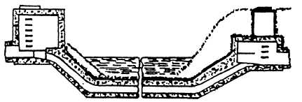
Figure 2-21.—An inverted siphon.
to convey domestic and industrial wastes and to
transport them to a wastewater treatment plant. The
purpose of these systems is to safeguard public health
by preventing disease-producing bacteria, viruses, and
parasites getting into groundwater or drinking water
systems. A description of the various elements and
structures used in a wastewater system is as follows:
1. SANITARY SEWER. A sanitary sewer system
carries mostly domestic wastes but may carry some
industrial waste. These systems are NEVER designed to
carry storm water or groundwater. (To convey storm
water, groundwater, or other surface water to disposal
points, a storm sewer system is designed and
constructed separately from the sanitary sewer system.)
Sanitary sewer system piping includes the following:
a. BUILDING, OR HOUSE, SEWER. A
service-connection pipe that connects an individual
building to the wastewater system. These pipes are 4
inches or larger in diameter and are commonly concrete,
cast iron, or plastic. The building, or house, sewer is the
smallest pipe in a wastewater collection system. All
other pipes must be a MINIMUM of 8 inches in
diameter.
b. LATERAL SEWER. Piping that receives
discharge from house sewers.
c. SUBMAIN, OR BRANCH, SEWER. A pipe
that receives waste from two or more lateral sewers.
d. MAIN, OR TRUNK, SEWER. A pipe that
takes discharge from two or more submains or from a
submain plus laterals.
e. INTERCEPTING SEWER. One that
receives wastewater from more than one main, or trunk
sewer.
f. RELIEF SEWER. A sewer built to relieve an
existing sewer that has an inadequate capacity.
2. LIFT STATION. Most piping in a wastewater
system consists of gravity pipes that are designed to flow
2-20
by gravity action at a rate of not less that 2 feet per
second. Where gravity flow is not practical or possible,
a lift station, such as the one shown in figure 2-20, is
constructed to pump wastewater to a higher level. From
the lift station, the wastewater is pumped through a pipe,
called a force main, to higher elevation gravity pipes.
Unlike gravity piping, force mains always flow
complete] y filled and under pressure.
3. INVERTED SIPHON. Another sewer pipe
designed to flow full and under pressure is the inverted
siphon. These pipes dip below the designed gradient of
the gravity pipes and are used to avoid obstacles, such
as open-cut railways, subways, and streams. An
example of an inverted siphon is shown in figure 2-21.
The inverted siphon may have one, two, or more pipes
and is designed to flow at a rate of at least 3 feet per
second to keep the pipe(s) clear of settleable solids. It
should have manholes constructed at both ends for
maintenance.
4. MANHOLE. A manhole is a concrete or
masonry structure used for inspection and maintenance
of sewer lines. Examples of manholes are shown in
figure 2-22. The bottom portion of a manhole is usually
cylindrical and has an inside diameter of at least 4 feet.
The upper portion usually tapers to the street or ground
surface and is fitted with a cast-iron cover. For proper
sewage flow, the bottom of the manhole slopes toward
a built-in charnel that has a depth of three fourths of the
diameter of the sewer pipe. For sewers up to
approximate] y 60 inches in diameter, manholes are
usually spaced 300 to 400 feet apart. They are also
required at all locations where sewer lines intersect or
where the sewer lines change direction, grade, or pipe
s i z e.
DESIGN
Design guidance for wastewater systems is
contained in Domestic Wastewater Control,
MIL-HDBK-1005/8.


