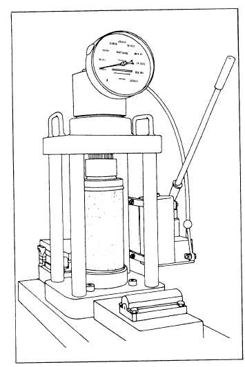
Figure 13-22.—Compression-testing machine.
the spherical seat. Check the operation of the machine.
Keep the previously prepared test specimen moist by
covering it with wet burlap during the period between
removing the specimen from the curing environment
and testing. That applies to each specimen you will test.
2. Determine the diameter of the test specimen to
the nearest 0.01 inch by averaging two diameters
measured at right angles to each other at midheight of
the cylinder. Measure the length, including caps, to the
nearest 0.1 inch. Record the dimensions on a prepared
data sheet.
3. Place the specimen on the lower bearing block,
bring the upper block almost to contact, and align the
axis of the specimen with the center of thrust of the
spherical head. Carefully and slowly bring the spherical
head into contact with the specimen, rotating the
movable portion gently by hand so that uniform seating
is obtained. Apply the test load continuously and
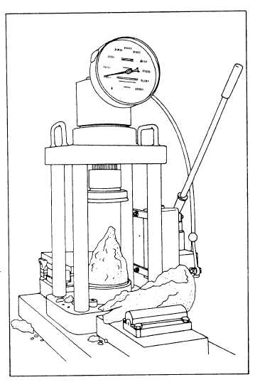
Figure 13-23.—Normal fracture of concrete test cylinder in
compression.
without shock at a rate of 20 to 50 pounds per square
inch (psi). Observe and record the maximum load during
the test. Observe the type of fracture and record any
unusual features. The normal cone type of fracture is
illustrated in figure 13-23.
4. Calculate the compressive strength of the
concrete using the following formula:
Where:
f´c =
P =
A =
compressive strength (in psi)
maximum load (in pounds)
cross-sectional area of specimen (in
inches)
13-31


