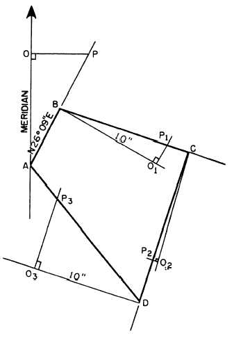
Figure 7-36.—Plotting traverse lines by parallel method from
a single meridian.
locate C. Proceed to locate D in the same manner. This
procedure leaves you with a number of light meridian
lines through stations on the plot. A procedure that
eliminates these lines is shown in figure 7-36. Here you
draw a single meridian NS, well clear of the area of the
paper on which you intend to plot the traverse. From a
convenient point O, you layoff each of the traverse lines
in the proper direction. You can then transfer these
directions to the plot by one of the methods for drawing
parallel lines.
PLOTTING ANGLES FROM TANGENTS.—
Sometimes instead of having bearing angles to plot
from, you might want to plot the traverse from
deflection angles turned in the field. The deflection
angles for the traverse you are working on are as
follows:
AB to BC
78°25'R
BC to CD
90°57'R
CD to DA
122°58'R
DA to AB
67°40'R
Figure 7-37.—Plotting by tangent-offset method from deflection
angles larger than 45°.
You could plot from these angles by protractor. Lay
off one of the traverse lines to scale; then lay off the
direction of the next line by turning the deflection angle
to the right of the firt line extension by protractor and
soon.
However, the fact that you can read a protractor
directly to only the nearest 30 minutes presents a
problem. When you plot from bearings, your error in
estimation of minutes applies only to a single traverse
line. When you plot from deflection angles, however,
the error carries on cumulatively all the way around. For
this reason, you should use the tangent method when
you are plotting deflection angles.
Figure 7-37 shows the procedure of plotting
deflection angles larger than 45°. The direction of the
starting line is called the meridian, following a
conventional procedure, that the north side of the figure
being plotted is situated toward the top of the drawing
paper. In doing this, you might have to plot the
appropriate traverse to a small scale using a protractor
7-25


