in this case, because each curve has two tangents rather
than a single long chord.
The coordinates of A, B, C, and D are the same as
in the first example, but the coordinates of the points of
intersection (PIs) must be established from the latitudes
and departures of the tangents. The computations for
determining the tangent bearings are shown in the lower
left of figure 7-34. When you have only the chord
bearing, you can compute the tangent bearing by adding
or subtracting one half of delta (A) as correct. The angle
between the tangent and the chord equals N2.
After setting coordinates on the PIs, you
cross-multiply, accumulate the products, subtract the
smaller from the larger, and divide by 2, as before, to get
the area of the straight-line figure running around the
tangents. You then add or subtract each external area as
appropriate. In figure 7-33, you can see that the external
area for Curve 1 is inside the parcel boundary and must
be added, while that of Curve 2 is outside and must be
subtracted. The area comes to 348,881 square feet,
which is an acceptable check on the area obtained by
using segmental areas.
Plotting Horizontal Control
Computations for horizontal control become greatly
clarified when you can see a plot (that is, a graphic
representation to scale) of the traverse on which you are
working. A glance at the plot of a closed traverse, for
instance, tells you whether you should add or subtract
the departure or the latitude of a traverse line in
computing the departure or latitude of an adjacent line
or in computing the coordinates of a station.
For linear distances that are given in feet and
decimals of feet, you use the correct scale on an
engineer’s scale for laying off linear distances on a plot.
For plotting traverses, there are three common methods:
by protractor and scale, by tangents, and by coordinates.
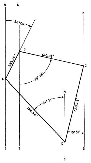
PLOTTING ANGLES BY PROTRACTOR
AND SCALE.— For the traverse on which you have
been working, the adjusted bearings and distances are
as follows:
Traverse Line
Bearing
Distance
AB
N26°09'E
285.14 feet
BC
S75°26'E
610.26 feet
CD
S15°31'W
720.28 feet
DA
N41°31'W
789.96 feet
Figure 7-35.—Traverse plotted by protractor-and-scale method.
Figure 7-35 shows the method of how to plot this
traverse with a scale and protractor. First select a scale
that will make the plot fit on the size of your paper. Select
a convenient point on the paper for stations A and draw
a light line NS, representing the meridian through the
station.
AB bears N26°9'E. Set the protractor with the
central hole on A and the 00 line at NS, and lay off
26°09'E. You will have to estimate the minutes as best
you can. Draw a line in this direction from A, and on the
line measure off the length of AB (285. 14 feet) to scale.
This locates station B on the plot. Draw a light line
NS through B parallel to NS through A, and representing
the meridian through station B. BC bears S75°26'E. Set
the protractor with the central hole on B and the 00 line
on NS, lay off 75°26' from the S leg of NS to the E, and
measure off the length of BC (610.26 feet) to scale to
7-24