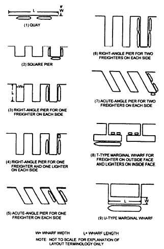
Figure 1-21.—Types of wharfage structures.
WHARFAGE STRUCTURES
Wharfage structures are designed to allow ships to
lie alongside for loading and discharge. Figure 1-21
shows various plan views of wharfage structures. Any
of these may be constructed of fill material, supported
by bulkheads. However, a pier or marginal wharf
usually consists of a timber, steel, or concrete
superstructure, supported on a substructure of timber-,
steel-, or concrete-pile bents.
Working drawings for advanced-base piers are
contained in Facilities Planning Guide, Volume 1,
NAVFAC P-437. Figures 1-22, 1-23, and 1-24 are
portions of the advanced-base drawing for a 40-foot
timber pier.
Each part of a pier lying between adjacent pile bents
is called a bay, and the length of a single bay is equal to
the on-center spacing of the bents. In the general plan
shown in figure 1-22, you can see that the 40-foot pier
consists of one 13-foot outboard bay, one 13-foot
inboard bay, and as many 12-foot interior bays as needed
to meet the length requirements for the pier.
The cross section shown in figure 1-24 shows that
each bent consists of six bearing piles. The bearing piles
are braced transversely by diagonal braces. Additional
transverse bracing for each bent is provided by a pair of
batter piles. The batter angle is specified as 5 in 12. One
pile of each pair is driven on either side of the bent, as
shown in the general plan. The butts of the batter piles
are joined to 12-inch by 12-inch by 14-foot longitudinal
batter-pile caps, each of which is bolted to the
undersides of two adjacent bearing-pile caps in the
positions shown in the part plan. The batter-pile caps are
placed 3 feet inboard of the center lines of the outside
bearing piles in the bent. They are backed by 6- by
14-inch batter-pile cap blocks, each of which is bolted
to a bearing-pile cap. Longitudinal bracing between
bents consists of 14-foot lengths of 3 by 10 planks,
bolted to the bearing piles.
Figure 1-22.—General plan of an advanced-base 40-foot timber pier.
1-12


