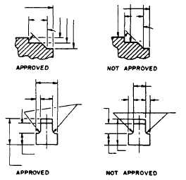
Figure 3-31.-Breaking extension lines and leaders at points
of intersection.
radius of an arc is to be indicated, there is an
arrow at only the end of the line that touches the
arc. The other end, without an arrow, terminates
at the point used as the center in drawing the arc.
The arrowhead on a dimension or leader line
is an important detail of a drawing. If these
arrowheads are sloppily drawn and vary in
size, the drawing will not look finished and
professional. The size of the arrowhead used on
a drawing may vary with the size of the drawing,
but all arrowheads on a single drawing should be
the same size, except occasionally when space is
very restricted.
The arrowheads used on Navy drawings are
usually solid, or filled in, and are between
one eighth and one fourth of an inch long, with
the length about three times the spread. (See
fig. 3-32.)
With a little practice, you can learn to make
good arrowheads freehand, Referring to figure
3-32, first define the length of the arrowhead
with a short stroke as shown at A. Then draw the
sides of the arrowhead as indicated at B and C.
Finally, fill in the area enclosed by the lines, as
shown at D.
LEADERS
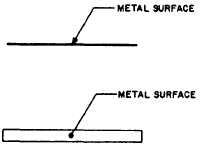
Leaders are used to connect numbers,
references, or notes to the appropriate surfaces
Figure 3-32.-Method of drawing an arrowhead.
or lines on the drawing. From any suitable
portion of the reference, note, or number, a short
line is drawn parallel to the lettering. From this
line the remainder of the leader is drawn at an
angle (dog leg) to an arrowhead or dot. In this
way, the leader will not be confused with other
lines of the drawing. If the reference is to a line,
the leader is always terminated at this line with
an arrowhead, as shown in figure 3-33. However,
a reference to a surface terminates with a dot
within the outline of that surface.
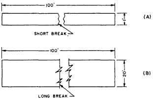
BREAK LINES
The size of the graphic representation of an
object is often reduced (usually for the purpose
of economizing on paper space) by the use of a
device called a break. Suppose, for example,
you want to make a drawing of a rectangle 1 ft
wide by 100 ft long to the scale of 1/12, or
1 in. = 1 ft. If you drew in the full length of the
rectangle, you would need a sheet of paper 100
in. long. By using a break, you can reduce the
length of the figure to a feasible length, as shown
in figure 3-34.
Figure 3-33.-Use of a leader.
Figure 3-34.-Use of proper line conventions for (A) short
break, and (B) long break.
3-23