On the original object, the ratio of width to
length is 1:100. You can see that on the drawing
the ratio is much larger (roughly about 1:8).
However, the break tells you that a considerable
amount of the central part of the figure is
presumed to be removed.
The thick, wavy lines shown in view (A), figure
3-34, are used for a short break. A short break
is indicated by solid, freehand lines, and is
generally used for rectangular sections. For
wooden rectangular sections, the breaks are made
sharper (serrated appearance) rather than wavy.
For long breaks, full, ruled lines with freehand
zigzags are used, as shown in view (B), figure 3-34.
For wider objects, a long break might have more
than one pair of zigzag lines.
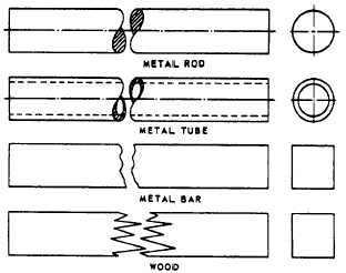
For drawings made to a large scale, special
conventions are used that apply to drawing breaks
in such things as metal rods, tubes, or bars. The
methods of drawing these breaks are shown in
figure 3-35.
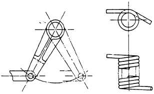
PHANTOM LINES
Phantom lines are used most frequently to
indicate an alternate position of a moving part,
as shown in the left-hand view of figure 3-36. The
part in one position is drawn in full lines, while
in the alternate position it is drawn in phantom
lines.
Phantom lines are also used to indicate a break
when the nature of the object makes the use of
the conventional type of break unfeasible. An
example of this use of phantom lines is shown in
the right-hand view of figure 3-36.
Figure 3-36.-Use of phantom lines.
SECTION LINES
Sometimes the technical information conveyed
by a drawing can best be shown by a view that
represents the object as it would look if part of
it were cut away. A view of this kind is called a
section.
The upper view of figure 3-37 shows a plan
view of a pipe sleeve. The lower view is a section,
Figure 3-35.-Use of special breaks.
3-24
Figure 3-37.-Drawing of a plan view and a full section.