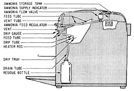
Figure 3-64.-Ammonia flow system.
tank through a gravity-feed system (fig. 3-64).
This feed system permits a smooth, even flow of
ammonia, thus minimizing the possibility of air
or vapor locking of the feed tubing. The amount
of ammonia fed into the developer is controlled
by a feed regulator at a rate of approximately 50
to 60 drops per minute. The ammonia is directed
into evaporating drip trays that are suspended in
the developer tank. Fastened to these trays are
electric heater rods. These rods, in conjunction
with a second thermo-switch controlled heater in
the developing tank, serve to heat the ammonia
and thereby accelerate the formation of ammonia
vapors. These vapors activate the image on the
print as they escape through the holes in the
upper part of the developer tank. Thus, a semi-
permanent image of those areas that were NOT
desensitized in the printing section is developed
on the print as it passes across the vapors.
To protect the machine from flooding with
ammonia when the machine is secured, an
automatic shutoff valve is located in the ammonia
feedline. This value shuts automatically when the
machine is secured and opens automatically when
the machine is turned on, thereby remitting
ammonia to the feed tray.
A second ammonia supply system being used
in some machines is called the anhydrous
ammonia system. Cylinders filled with anhydrous
ammonia supply the developing section with an
ammonia vapor. This vapor is directed into the
developer tank where it is distributed with the aid
of distilled water that is fed into the drip trays.
For safety reasons, cylinders should be stored
away from heat and sunlight. Do not allow the
temperature of the cylinders to reach a
temperature above 125°F. Position the cylinders
upright, and firmly attach them with a chain or
strap to a rigid supporting member, such as a wall.
Cylinders are attached to the developing tank
through a system of piping and fittings, When
changing a cylinder, close the valve on the
expended cylinder tightly by turning it clockwise.
Bleed off all pressure remaining in the feed line
by turning on the ammonia flow in the machine.
Disconnect the fitting or yoke cylinder connection.
Replace the cylinder and remove the protecting
valve cap. Ensure that a Teflon washer is in place.
Connect the fitting or yoke cylinder connection.
Make sure all connections are tight. Open the
cylinder valve. Check for possible leaks on all
connections by holding a piece of unexposed and
undeveloped diazo paper close to the connections.
If the diazo paper discolors, retighten the
connections.
A uniform flow of ammonia is maintained by
a pressure gauge located between the cylinder and
the developing section. In addition, the pressure
gauge indicates the amount of available ammonia
left in the cylinder. A new cylinder will have a
gauge reading of 150, while an empty cylinder will
indicate a reading of 50.
3-48