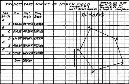
Figure 13-12.-Sample field notes from a deflection angle transit-tape survey.
2. Read the vernier with the eye directly over
the top of the coinciding graduations to eliminate
the effects of parallax.
3. Take the reading of the other vernier as a
check. The readings should be 180° apart.
4. Check the plate bubbles before measuring
an angle to see if they are centered, but do not
disturb the leveling screws between the initial and
final settings of the line of sight. If an angle is
measured again, the plate may be releveled after
each reading before sighting again on the starting
point.
5. Make sure that the rodman is holding the
range pole truly vertical when you sight at it.
When the bottom of the range pole is not visible,
let the rodman use a plumb bob.
6. Avoid accidental movement of the horizon-
tal circle; for instance, moving the wrong clamp
or tangent screw. If a number of angles will be
observed from one setup without moving the
horizontal circle, you should sight at some clearly
defined distant object that will serve as a reference
mark and take note of the angle. Occasionally,
you should recheck the reading to this point
during measurement to see if there is any
accidental movement.
An example of a horizontal deflection angle
measurement is shown in figure 13-12. The field
notes contain data taken from a loop traverse
shown in the sketch. The transit was first set up
at station A, and the magnetic bearing of AB was
read on the compass. Then the deflection angle
between the extension of EA and AB was turned
in the following manner:
1. The instrumentman released both clamps,
matched the vernier to zero by hand, tightened
the upper motion clamp, and set the zero exactly
with the upper tangent screw.
2. With the telescope plunged (inverted
position), the instrumentman sighted the range
pole held on station E. Then he tightened the
lower motion clamp and manipulated the lower
motion tangent screw to bring the vertical cross
hair to exact alignment with the range pole.
3. The instrumentman replunged the telescope
and trained on the extension of EA. (Notice that
the telescope is in its normal position now.) He
then released the upper motion and rotated the
telescope to the right until the vertical cross hair
came into line with the range pole held on
station B. He further set the upper motion clamp
screw and brought the vertical cross hair into
exact alignment with the range pole by manipu-
lating the upper motion tangent screw.
4. The instrumentman then read the size of
the deflection angle on the A vernier (89°01´).
Since the angle was turned to the right, he
recorded 89°01´R in the column headed “Defl.
Angle.”
Likewise, he recorded the chained
distance between stations A and B and the
magnetic bearing of traverse line AB under their
appropriate headings.
13-11