is set up at B, and a 90° angle is turned from line
AB. The distance BB´ is carefully measured and
recorded. The instrument is moved to B´, and
another 90° angle is turned. B´C´ is laid off to
clear the obstacle. The instrument is moved to C,
and a third 90° angle is turned. Distance CC´,
equal to BB´, is measured and marked. This
establishes a point C on the original line. The
instrument is moved to C, and a fourth 90° angle
is turned to establish the alignment CD that is the
extension of AB beyond the obstacle.
When the distance to clear the obstacle, BB´
or CC´, is less than a tape length, you can avoid
turning four 90° angles as follows: Erect perpen-
dicular offsets from points A and B in figure 13-18
so that AA´ equals BB´. Set up the instrument at
B’, and measure angle A´B´B to be sure that it’s
90°. Extend line A´B´ to C´ and then to D´,
making sure that point C clears the obstacle.
Then, lay off perpendicular offset C´C equal to
AA´ or BB´ and perpendicular offset D´D equal
to C´C. Then, line CD is the extension of line AB.
The total distance of the line AD is the sum of
the distances AB, B´C´, and CD.
You also compute the diagonals formed by the
end rectangles and compare the result to the
actual measurement, if you can, as a further
check.
Line Between Nonintervisible Points
Sometimes you need to run a straight line
between nonintervisible points when events make
the use of the above methods of bypassing an
obstacle impractical. If there is an intermediate
point on the straight line from which both of the
end points can be observed, the method called
BALANCING IN (also called BUCKING IN,
JIGGLING IN, WIGGLING IN, or RANGING
IN) may be used.
A problem often encountered in surveying is
to find a point exactly on the line between two
other points when neither can be occupied or when
an obstruction, such as a hill lies between the two
points. The point to be occupied must be located
so that both of the other points are visible from
it. The process of establishing the intermediate
point is known as wiggling in or ranging in.
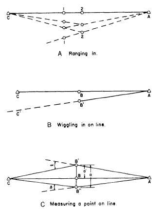
The approximate position of the line between
the two points at the instrument station is first
estimated by using two range poles. The range
poles are lined in alternately in the following
manner. In figure 13-19, view A, set range pole
1 and move range pole 2 until it is exactly on line
between pole 1 and point A. You do this by
Figure 13-19.-Setting up on a line between two points.
sighting along the edge of pole 1 at the station
A until pole 2 seems to be on line. Set range pole
2 and move pole 1 until it is on line between pole
2 and point C. Now, move pole 2 into line again,
then pole 1, alternately, until both are on line AC.
The line will appear to pass through both poles
and both stations from either viewing position.
After finding the approximate position of the
line between the two points, you set up the
instrument on this line. The instrument probably
will not be exactly on line, but will be over a point,
such as B´, (see fig. 13-19, view B). With the in-
strument at B´, you backsight on A and plunge
the telescope and notice where the line of sight
C passes the point C. Estimate this distance CC´
and also the distance that B´ would be away from
C and A. Estimate the amount to move the
instrument to place it on the line you need. Thus,
if B´ is midway between A and C, and C´ misses
C by 3 feet to the left, B´ must be moved about
1.5 feet to the right to reach B. Continue the
sequence of backlighting, plunging the telescope,
and moving the instrument until the line of sight
13-16