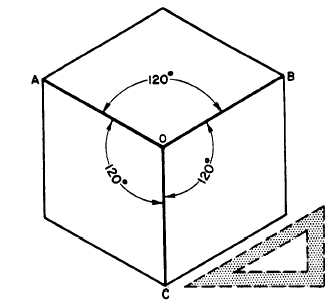
Figure 5-37.-Isometric projection of a cube.
that the figure has a central axis, formed by the
lines OA, OB, and OC. The existence of this axis
is the origin of the term axonometric projection.
In an isometric projection, each line in the axis
forms a 120-degree angle with the adjacent line,
as shown. A quick way to draw the axis is to draw
the perpendicular OC, then use a T square and
30°/60° triangle to draw OA and OB at 30 degrees
to the horizontal. Since the projections of parallel
lines are parallel, the projections of the other
edges of the cube will be, respectively, parallel to
these axes.
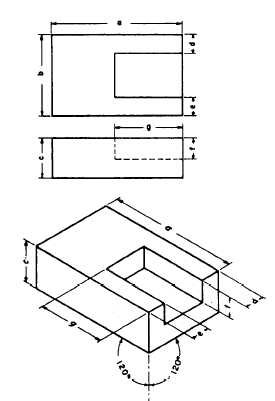
A rectangular object can be easily drawn in
isometric by the procedure known as box
construction. In the upperpart of figure 5-39,
there is a two-view normal multi-view projection
of a rectangular block. An isometric drawing of
the block is shown below. You can see how you
build the figure on the isometric axis and how you
lay out the dimensions of the object on the
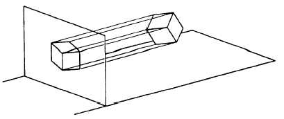
Figure 5-38.-Use of an isometric axis.
isometric drawing. Because you lay out the
identical dimensions, it is an isometric drawing
rather than an isometric projection.
Non-isometric Lines.— If you examine the
isometric drawing shown in figure 5-39, you will
note that each line in the drawing is parallel to
one or another of the legs of the isometric axis.
You will also notice that each line is a normal line
in the multi-view projection. Recall that a
normal line is a line that, in a normal multi-view
projection, is parallel to two of the planes of
projection and perpendicular to the third. Thus,
Figure 5-39.-Use of “box construction” in isometric
drawing.
5-21