an elliptical edge. To make an isometric drawing
of this block, draw the circumscribing rectangle
on the top multi-view view, lay off equal
intervals as shown, and draw perpendiculars at
these intervals from the upper horizontal edge of
the rectangle to the ellipse. Then draw the
rectangle in isometric, as shown below, and plot
a series of points along the elliptical edge by
laying off the same perpendiculars shown in the
top multi-view view. Draw the line of the ellipse
through these points with a french curve.
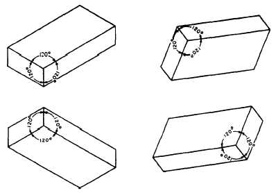
Alternate Positions of Isometric Axis.— Up
to this point, the isometric axis has been
used with the lower leg vertical. The axis
may, however, be used in any position, pro-
vided the angle between adjacent legs is always
120 degrees. Figure 5-44 shows how varying the
position of the axis varies the view of the object.
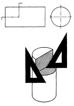
Diagonal Hatching in Isometric.— Diagonal
hatching on a sectional surface shown in isometric
should have the appearance of making a 45-degree
angle with the horizontal or vertical axis of the
surface. If the surface is an isometric surface (one
that makes an angle of 35°16’ with the plane of
projection), lines drawn at an angle of 60 degrees
to the horizontal margin of the paper, as shown
in figure 5-45, present the required appearance.
To show diagonal hatching on a non-isometric
surface, you must experiment to determine the
angle that presents the required appearance.
DIMETRIC AND TRIMETRIC PROJEC-
TION.— TWO other subclassifications of the
Figure 5-45.-An example of diagonal hatching in isometric.
axonometric projection category are dimetric and
trimetric projections; however, these types are used
less frequently than isometric projections and will
not be discussed further in this training manual.
OBLIQUE SINGLE-PLANE
PROJECTION
We have seen that an object may be drawn
showing length and width on a single plane. Depth
Figure 5-44.-Various positions of isometric axes.
5-24


