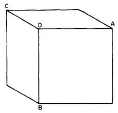
may be drawn from O at any convenient angle.
All three are equal in length, the length being the
length of an edge of the original cube (which may
be scaled down or up if the drawing is made other
than full scale). After you draw the axis,
complete the projection by drawing the required
parallel lines. All the edges shown in the
projection are, like the edges on the original cube,
equal in length.
Cabinet Projection
The first thing you notice about the cube
shown in figure 5-48 is the fact that it doesn’t look
like a cube because the depth dimension appears
to be longer than the height and width dimensions.
The reason for this is the fact that a cavalier
projection corrects a human optical illusion—the
one that causes an object to appear to become
smaller as its distance from the eye increases. This
illusion. in turn. causes receding parallel lines to
appear to the eye to be shorter-than they really
are, and also to be converging toward a point in
the distance. But receding parallel lines on a
cavalier projection appear in their true lengths,
and they remain constantly parallel. Also, the far
edges of the cube shown in figure 5-48 are equal
in length to the near edges.
The distortion in figure 5-48 is only apparent.
It is sometimes desirable to reduce this appearance
of distortion. This can be done by reducing the
length of the receding axis (OC in fig. 5-39).
This axis can be reduced by any desired amount,
but it is customary to reduce it by one half.
Figure 5-49.-Cabinet projection of the cube in figure 5-48.
(Note receding axis OC reduced by one half its
length.)
When the receding axis is reduced by one half,
the projection is called a CABINET PROJEC-
TION. Figure 5-49 shows a cabinet projection
of a cube. The length of the receding axis OC has
been reduced by one half. As you can see, this
representation looks more like a cube.
Cavalier and cabinet projections are compared
in figures 5-50 and 5-51.
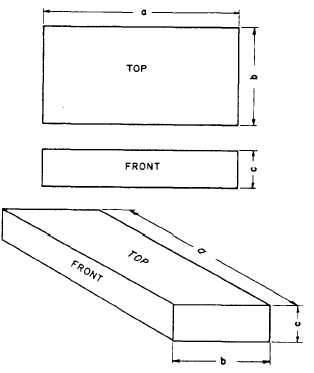
Oblique Drawing Techniques
In an oblique projection drawing of a
rectangular object, one face (usually the most
prominent or most important) is parallel to the
plane of projection. All features appearing on this
plane, such as circles or oblique lines, are in their
true dimension. However, in the side or top views,
these same features are somewhat distorted
because of the receding axis angle. When drawing
these features, you can use various techniques to
aid you in their construction.
For convenience, the angles chosen for the
receding axis are either 30 degrees, 45 degrees, or
Figure 5-50.-Cavalier projection. Distances along front axis
and along receding axis are all true.
5-26