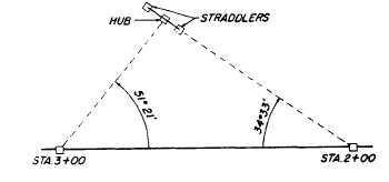
Figure 13-25.-Setting a point by the use of straddlers.
use a pair of straddle hubs (commonly called
STRADDLERS), as shown in figure 13-25. Here
the point was to be located at an angle of 34°33´
from station 2 + 00 and at an angle of 51°21´
from station 3 + 00. The transit was set up at
station 2 + 00, sighted on station 3 + 00, and an
angle of 34°33´ was turned to the right. On this
line of sight, a pair of straddle hubs was driven,
one on either side of the estimated point of inter-
section of the tie lines. A cord was stretched
between the straddlers.
The transit was then shifted to station 3 + 00,
sighted on station 2 + 00, and an angle of 51°21´
was turned to the left. A hub was driven at the
point where this line of sight intercepted the cord
between the straddlers.
Setting Points When Given
an Angle from One Station and
the Distance from Another
To set a point with a given angle from one
station and the distance from another, you would
find it best to determine the direction of the
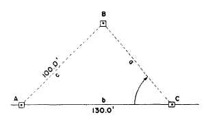
distance line by triangle solution. In figure 13-26,
Figure 13-26.-Locating a point by angle and distance from
two stations.
point B is to be located 100.0 ft from station A
and at an angle of 50°00´ from station C.
In this example, you can determine the size
of the angle at A by first determining the size of
angle B, then subtracting the sum of angles B and
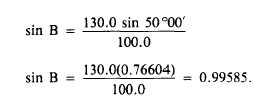
C from 180°. The solution for angle B is as
follows:
Angle B then measures, to the nearest minute,
84°47´. Therefore, angle A measures
Set up a transit at A, sight on C, and turn
45°13´ to the left. Then, you set B by measuring
off 100.0 ft on this line of sight. As a check, you
set up the transit at C, sight on A, turn 50°00´
to the right, and make sure this line of sight
intercepts the marker at B.
TRANSIT-TAPE SURVEY
The exact method used in transit-tape survey
may vary slightly, depending upon the nature of
the survey, the intended purpose, the command
or unit policy, and the preferences of the survey
party chief. The procedures presented in this
section are customary methods described in
general terms.
SELECTING POINTS FOR MARKING
All points where a traverse changes direction
are marked, usually with a hub that locates the
station exactly, plus a guard stake on which
the station of the change-of-direction point is
inscribed, such as 12 + 35. In the expression
“station 12 + 35,” the 12 is called the full
station and the 35 is called the plus.
The points that are to be tied to the traverse
or set in the vicinity of the traverse are usually
selected and marked or set as the traverse is
run. The corresponding tie stations on the
traverse are selected and marked at the same
time. The first consideration in selecting tie
stations is VISIBILITY, meaning that tie stations
and the point to be tied or set must be inter-
visible. The next is PERMANENCY (not easily
13-20


