displaced. Another advantage is that reproductions of
the cut sheet can be given to construction supervisors
so that they may always have access to all the essential
construction data.
AIRFIELD SURVEYS
Airfield construction is of a special kind; for this
reason, it is discussed here under a separate heading.
AIRFIELD ROUTE SURVEYS
The route for an airfield is the horizontal location
of the runway center line; if there is more than one
runway, there is, of course, more than one route. The
principal consideration regarding the direction of a
runway center line is the average direction of the
prevailing wind in the area, since planes must take off
into the wind. The azimuth of the center line will be
as nearly as possible the same as the average azimuth
of the prevailing wind. A study of the meteorological
conditions is therefore a part of the reconnaissance
survey. Other data gathered on this survey (which may
be conducted on foot, by ground surface vehicle, by
plane, or by all three) include the land formation,
erosional markings, vegetation, configuration of
drainage lines, flight hazards, approach zone
obstructions, and soil types.
From the reconnaissance data, one or more
preliminary center lines are selected for location by
preliminary survey. For quick preliminary stakeout,
there may be two parties, working away from station
0 + 00 located at the approximate midpoint of the
center line. In such cases, stations along the azimuth
may be designated as plus and those along the back
azimuth as minus.
Level parties follow immediately behind the
transit parties, taking profile levels and cross sections
extending the width of the strip, plus an overage for
shoulders and drainage channels. From the
preliminary survey data, a plan and profile are made
of each tentative location, and from these, a selection
of a final location is made.
AIRFIELD STAKEOUT
Airfield runways, taxiways, hardstands, and
aprons are staked out much as a highway is staked out.
There are, however, certain special considerations
applying to approach zones.
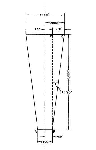
As you know from chapter 3, an approach zone is
a trapezoidal area beyond the end zone at each end of
a runway. It must be free of obstruction not only on
the ground but also off the ground at a specific glide
angle. The size of the approach zone depends on the
type and stage of development of the field. For
permanent naval air stations, the trapezoidal area
might be 10,000 feet long with a width of 4,000 feet
at the outer end. For purposes of explanation only, we
will assume that these are the dimensions of the
approach zone for which you are surveying.
The glide angle for most types of aircraft is 2
percent, usually given as 50:1, or a rise (or drop) of 1
vertical for 50 horizontal. Figure 10-25 shows, in
plan, profile, and isometric, an approach zone and its
adjacent transition surfaces and end of runway. You
must stake out this approach zone and check it for
clearance by the following procedure:
Figure 10-26 shows the approach zone in plan.
The dotted line BC lies 750 feet from the center line.
The angle at B can be determined by solving the
Figure 10-26.—Plan view of approach zone.
10-25


