
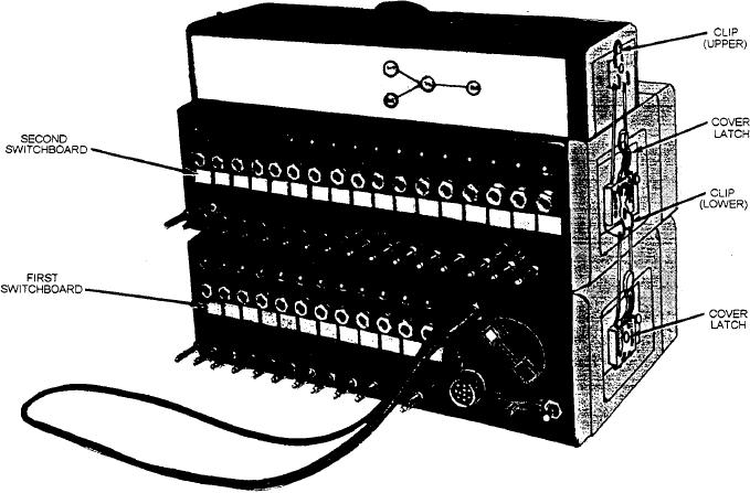
Figure 11-26.--Installation arrangement for two switchboards.
To operate your switchboard in the dark, pull out on
you can ring back the calling party (fig. 11-25, view D).
the lamp cap and turn the lamp on. Remember, though,
You do this by removing the plug of the operator's cord
when the lamp is lighting the switchboard, the night
from the operator's jack on the operator's pack and
alarm cannot be used at the same time.
inserting it into the calling party's jack. Operate the
RING BACK-PWR RING FWD switch to the RING
BACK, turn the hand-ringing generator rapidly
STACKING OF TWO SWITCHBOARDS
approximately 10 turns. Remove the operator's plug
from the calling party's jack and insert it into the
To serve more than 12 but fewer than 30 lines, stack
operator's jack when both parties answer.
the 12-line switchboards. Remove the operator's pack
from the switchboard and install five line packs in the
If the called party disconnects before the
empty space. Place this modified switchboard on top of
conversation is completed, remove the plug of the
a normally equipped switchboard. Use two jumpers to
operator's cord from the operator's pack and insert it
connect the two switchboards. One jumper must be
into the jack of the calling party's line jack Operate the
connected to the NA binding posts of both switchboards,
hand-ringing generator rapidly about 10 turns. Remove
the plug of the operator's cord from the jack of the
and the other jumper must be connected to the GND
calling party's line jack and insert it into the operator's
binding posts of both switchboards. Be sure that the
jack on the operator's pack after both parties have
jumpers pass through the slot at the side of each
answered.
switchboard. Only one set of batteries is required to
serve both switchboard; remove the battery case from
If you must leave the switchboard, move the visual
the one containing the 17 line packs (from which the
and audible alarm switch (fig. 11-1 8) from VIS to AUD.
operator's pack has been removed). The field telephones
The alarm is silent on VIS, but audible on AUD. When
can then be connected. A maximum of 29 lines can be
the alarm is not required, place the VIS/AUD switch in
served with this arrangement as shown in figure 11-26.
the OFF position.
11-25