3. Keeping both tick marks together, place the
point of the pencil on the tick mark of the paper to hold
it in place. Pivot the paper until another straight portion
is aligned and make another mark on both map and
paper.
4. Continue in this manner until the measurement
is complete. Then place the paper on the graphic scale
and read the ground distance.
The RATIO-TYPE SCALE is simply a comparison
between a given distance measured on the map and on
the ground. It is independent of any unit of measure.
A scale of 1/25,000 means that one unit of measure on
the map is equal to 25,000 of the same units of
measure on the ground. The ground distance between
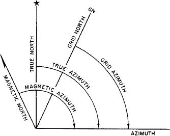
Figure 5-21.--True, magnetic, and grid azimuths.
two points may be determined by measuring between
the points on the map and multiplying the map
measurement by the scale. For example, the distance
commonly used in artillery, tank, and mortar gunnery. It
between two bridges on a certain map is 15 inches.
is convenient for many practical uses because it is
The scale of the map is 1:50,000. Therefore, the actual
approximately one unit of length at a distance (range) of
distance on the ground is found by multiplying 15
one thousand units.
inches by 50,000 (15 times 50,000 equals 750,000
inches). If this is to mean anything to you, change it
Base Line
to units that can be easily pictured in your mind. These
units might be feet, yards, meters, kilometers, or
In order to measure anything, there must always be
miles. To change the 750,000 inches to feet, you need
a starting point, or zero measurement. To express a
to divide by 12 (the number of inches in a foot); hence
direction as a unit of angular measure, there must be a
750,000 divided by 12 equals 62,500 feet. To change
starting point, or zero measure, and a point of reference.
the 62,500 feet to miles, divide again by 5,280 (the
These two points designate the base, or reference, line.
number of feet per mile); thus 62,500 divided by 5,280
There are three base linestrue north, magnetic north,
equals 11.8 miles.
and grid north. Those most commonly used are
By using either of the methods described above, you
magnetic and grid; the magnetic when working with a
can determine the distance between any two points.
compass, and the grid when working with a military
map.
Direction
TRUE NORTH. This is a line from any position on
the surface of the earth to the North Pole. All lines of
Directions are expressed in everyday life as right,
longitude are true north lines. True north is usually
left, straight ahead, and so forth. But the question arises,
symbolized by a star (fig. 5-21).
To the right of what? Military personnel require a
MAGNETIC NORTH. The direction to the
method of expressing a direction that is accurate,
magnetic North Pole is indicated by the north-seeking
adaptable for use in any area of the world, and has a
needle of a magnetic instrument. Magnetic north is
common unit of measure.
usually symbolized by a half arrowhead (fig. 5-21).
Directions are expressed as units of angular
GRID NORTH. This is the north established by the
measure, and there are several systems used.
vertical grid lines on the map. Grid north may be
1. The most commonly used unit of angular
symbolized by the letters GN (fig. 5-21).
measure is the degree with its subdivisions of minutes
and seconds.
Topographic Map Symbols
2. Another unit, less frequently used, is the mil
(abbreviated m). For the U.S. military Purposes, a
The purpose of a topographic map is to permit you
complete circle is divided into 6,400 mils. The mil is
to visualize an area of the surface of the earth with
5-16

