Figure 10-23.—Development of a sectional view.
arrangement, construction methods, and material
composition of the walls of the building.
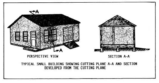
When a cutting plane is passed through the
narrow width of a building, as shown in figure
10-23, a TRANSVERSE, or CROSSSECTION,
is developed. Similarly, passing the cutting plane
through the length of a building results in a
LONGITUDINAL SECTION. These section,
usually located in the architectural division, are
used to clarify the building design and total
construction process. Another example of a
building section is shown in figure 10-24,
view A. Often, transverse and longitudinal
sections are drawn at the same scale as the floor
plan. To show as much construction information
as possible, it is not uncommon for staggered
(offset) cutting planes to be used in developing
these sections.
If the time and effort were spent to draw a
separate section for each and every wall and part
of a building, it would soon become apparent that
many of these sections are completely identical.
To reduce the time and effort required for
drafting and to simplify the construction
drawings, it is common practice to use typical
sections where exact duplications would otherwise
occur. An example of a typical section is shown
in figure 10-24, view B.
For best results and to save time, you should
make a sketch of the section before beginning
the actual drawing. Always have your sketch
checked by your leading petty officer or another
experienced EA to make sure that your work is
compatible with their concept of the design of the
building.
When more than one section is placed on the
drafting sheet, arrange the sections so that the first
one is through the front of the building, the other
sections, excluding the last, move progressively
through the interior, and the last one is
through the back. This way, when the sections are
finished, they give the user an orderly con-
struction “tour” through the building. The
following procedures will guide you in the
development of a section:
1. After having selected the appropriate scale,
lay out the first section lightly. Next, lay out all
the other sections, allowing enough space between
them for notes and dimensions. Align the sections
so that the same elevation is maintained and the
sections relate to one another, as shown in figure
10-22. Again, maintain enough clearance for sub-
titles and scale and enough room for your title
block.
2. Lay out the guidelines for the material
labels, leaders, and vertical dimensions.
3. Darken the section drawings, using a
system such as starting at the top of the sheet and
working down, then starting at the left and
10-28