used to indicate the direction in which the sections
are viewed. The cutting plane may be a single
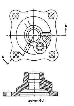
continuous plane, or it may be offset if the detail
can be shown to better advantage. On simple
views, the cutting plane should be indicated as
shown in figure 3-38, view A. On large, complex
views or when the cutting planes are offset, they
should be shown as in figure 3-39.
All cutting plane indications should be
identified by use of reference letters placed at
the point of the arrowheads. Where a change in
direction of the cutting plane is not clear,
reference letters may also be placed at each change
of direction. Where more than one sectional view
appears on a drawing, the cutting plane
indications should be lettered alphabetically.
The letters that are part of the cutting plane
indication should always appear as part of the
title; for example, SECTION A-A, SECTION
B-B, If the single alphabet is exhausted, multiples
of letters maybe used. The word SECTION may
be abbreviated, if desired. Place the title directly
under the section drawing.
DATUM LINES
A datum line is a line used to indicate a line
or plane of reference, such as the plane from
65.26
Figure 3-39.-Use of an offset section.
which an elevation
consist of one long
(medium thickness),
is measured. Datum lines
dash and two short dashes
equally spaced. Datum lines
differ from phantom lines only in the way they
are used.
STITCH LINES
Stitch lines are used to indicate the stitching
or sewing lines on an article. They consist of a
series of very short dashes (medium thickness),
approximately half the length of the dash of
hidden lines, evenly spaced. Long lines of stitching
may be indicated by a series of stitch lines
connected by phantom lines.
MATCH LINES
Match lines are used when an object is
too large to fit on a single drawing sheet
and must be continued on another sheet. The
points where the object stops on one sheet and
continues on the next sheet must be identified
with corresponding match lines. They are medium
weight lines indicated with the words MATCH
LINE and referenced to the sheet that has
the corresponding match line. Examples of
construction drawings that may require match
lines are maps and road plans where the length
is much greater than the width and it is
impractical to reduce the size of the drawing to
fit a single sheet.
ORDER OF PENCILING
Experience has shown that a drawing can be
made far more efficiently and rapidly if all the
lines in a particular category are drawn at the
same time, and if the various categories of lines
are drawn in a specific order or succession.
Figure 3-40 shows the order in which the lines
of the completed drawing (shown in the last
view) were drawn. This order followed the
recommended step-by-step procedures, which is
as follows:
1. Draw all center lines.
2. Draw the principal circles, arcs, fillets,
rounds, and other compass-drawn lines. A fillet
is a small arc that indicates a rounded concave
joint between two surfaces. A round is a small
arc that indicates a rounded convex joint between
two surfaces.
3-26