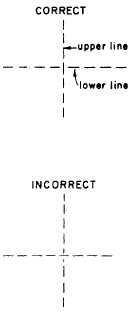
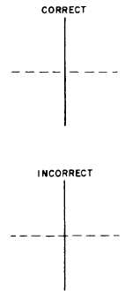
the incorrect procedure is shown in the lower
views.
Figure 3-28 shows an intersection between a
hidden edge line and a visible edge line. Obviously,
on the object itself the hidden edge line must be
below the visible edge line. You indicate this face
by drawing the hidden edge line as shown in the
upper view of figure 3-28. If you drew it as
indicated in the lower view, the hidden edge line
would appear to be above, rather than beneath,
the visible edge line.
Figure 3-29 shows an intersection between two
hidden edge lines, one of which is beneath the
other on the object itself. You indicate this fact
by drawing the lines as indicated in the upper view
of figure 3-29. If you drew them as indicated in
the lower view, the wrong line would appear to
be uppermost.
EXTENSION LINES
Extension lines are used to extend dimensions
beyond the outline of a view so that they can be
read easily. These thin, unbroken lines are started
about one sixteenth of an inch from the outline
of the object and extend about one eighth of an
inch beyond the outermost dimension line. They
are drawn parallel to each other and perpendicular
Figure 3-29.-Correct and incorrect procedures for draw-
ing intersecting hidden edge lines that are on different
levels.
Figure 3-30.-Use of extension lines.
to the distance to be shown. (See fig. 3-30.) In
unusual cases, extension lines may be drawn at
other angles if their meaning is clear.
As far as practical, avoid drawing extension
lines directly to the outline of an object.
When it is necessary for extension lines to cross
each other, they should be broken, as shown in
figure 3-31.
DIMENSION LINES
A dimension line, terminating at either end in
a long, pointed arrowhead, is inserted between
each pair of extension lines. It is a thin line, and,
Figure 3-28.-Correct and incorrect procedures for draw-
except in architectural
ing a hidden edge line that intersects a visible edge
is usually broken to
line.
dimension numerals.
3-22
and structural drafting, it
provide a space for the
Occasionally, when the


