vertical line in the left side view represents the
back face. Again, there is a line that appears as
a visible line in the right side view and as a
hidden line in the left side view.
In the back view, the block is shown reversed,
so that the cutaway part, which appears to the
right in the front view, appears to the left in the
back view. Similarly, the right-hand vertical line
in the front view represents the right side of the
block, while the right-hand vertical line in the back
view represents the left side.
As a general observation, it is helpful in view
analysis to note that in the top, bottom, and side
views, the line that represents the front face of
the block faces toward the front view of the block.
Similarly, in the back view, the line that represents
the left side faces toward the left side view of the
block. This applies to third-angle projection only.
A point that constitutes a corner on an
object is sometimes numbered for purposes of
identification in various views of the object. In
a particular view of an object, a corner point
number may be visible, or it may be hidden, as
shown in figure 5-18. In the upper left corner of
the figure, there is an oblique projection of a
block, with a corner numbered 2. You can see that
this corner is visible in top, back, and left side
views, but hidden in bottom, front, and right side
views.
The rule for numbering is that for a hidden
corner point, the number is placed within the
outline, and for a visible corner point, outside
the outline. You can see how the rule has been
followed in figure 5-18.
A multi-view projection should contain only
as many views as are required to describe the
object fully. If you refer back to figure 5-17,
you can see at once that the back view
does not convey any information that is
not available in the front view; the back
view is therefore superfluous and should be
omitted. The same applies to the bottom view,
which conveys no information not available
in the top view. Likewise, the left side view
conveys no information not available in the right
side view.
You have the choice of omitting either the top
or bottom view and either the right side or left
side view. One general rule in this instance is that
a top view is preferable to a bottom view and a
right side view, to a left side view; another rule
is that a view with a visible line is preferable to
a view with the same line shown as a hidden line.
Both rules apply here to eliminate the bottom and
the left side views. All you need here is a
three-view projection showing the top, front, and
right side views.
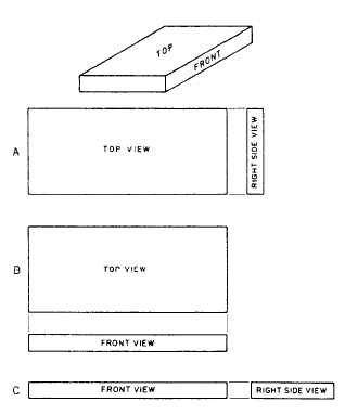
It is often the case that a two-view projection
is all that is required. The view at the top of figure
5-19 shows a single-view projection of an object.
It is obvious that a top view of this object tells
you everything you need to know except the
thickness; a right side view tells you everything
you need to know except the length; and a front
view tells you everything you need to know
except the width. All you need to do, then, is to
select a particular view and couple it with another
view that gives you the dimension that is missing
in the first view.
There are three possible two-dimensional
projections of the object shown in A, B, and C.
In the selection of one of these three, everything
else being equal, the balance of the drawing would
be the deciding factor. Either A or B appears
better balanced than C, and between A and B,
A would look better on a long oblong sheet of
paper, and B, better on a shorter oblong sheet.
The object shown in figure 5-19 has a
definitely designated top and front; it follows that
the right and left sides are also definitely
designated. This is the case with many objects;
you have no choice, for example, with regard to
the top, bottom, front, and back of a house.
Figure 5-19.-Two-view multi-view projections.
5-11


