To facilitate the stakeout, set a stake at point h.
From h the locations of points j and k may be measured
and staked. The distance used is one half of the length
of the headwall as that length is shown on the design
plans. Set stakes at points F and G directly opposite
and on lines at right angles to the ends of the
headwalls. Set stakes similarly at L and M. Set grade
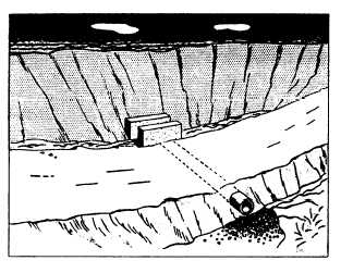
Figure 10-12.—Ditch inlet and pipe culvert
stakes near B and D for the invert or flow line of the
culvert.
The stakes set in this way are sufficient to locate
the forms for the headwalls and for the barrel of the
culvert. Figure 10-12 shows one of a number of types
of pipe inlets and culverts. The type shown is suitable
for picking up side-surface drains adjacent to a landing
strip or roadway embankment. Stakes for both
horizontal alignment and elevations are required.
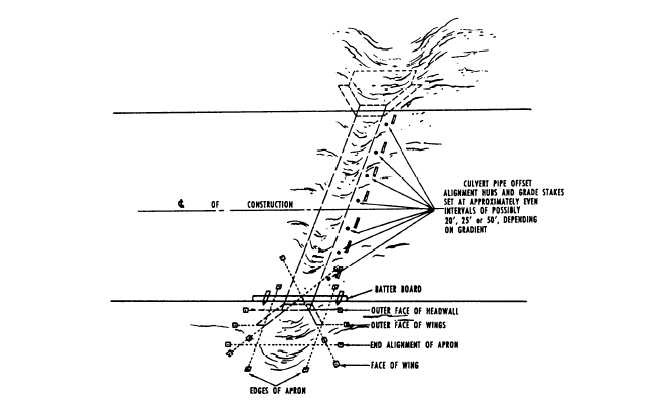
Figure 10-13 shows the stakeout of a pipe culvert,
wing wall, and apron.
BRIDGE SUBSTRUCTURES.— As you know
from chapter 2 of this TRAMAN, the substructure of
a fixed bridge consists of the end and intermediate
supports and their foundations. Bridge substructures
are divided into two main types of supports: end
supports called abutments and intermediate supports
called bents or piers.
Abutments.— The ground support at each end of
a bridge is called an abutment. Construction plans will
show the details of the abutments. Check the layout
after excavation and before pouring the concrete. You
must check abutment elevations, and when concrete is
used, establish lines for setting forms. Abutments
must be staked by following the construction plans,
Figure 10-13.—Stakeout of a pipe culvert, wing wall, and apron.
10-16


