and abutment stakes should be tied to the horizontal
control system to meet accuracy requirements.
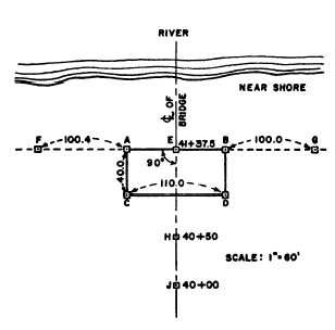
The following is a typical procedure for survey-
ing an abutment that is to be at right angles to the
center line of the bridge. In figure 10-14, the
foundation of a concrete abutment, ABDC, is shown
in the plan. AB is the face of the abutment foundation.
Establish two convenient points, H and J, near the
abutment CD, on the bridge center line. Set a stake at
E (station 41 + 37.50)—the station designated on the
plan for the abutment face.
Set up the transit at E, train on H, match the zeros,
and turn 90° angles to locate A and B at the correct
distance from E. Reference the line AB by setting
stakes at F and G at the indicated distances from A and
B. Set temporary stakes at C and D to mark the other
corners of the foundation.
Sometimes the alignment of a bridge is not at right
angles to the center line of the stream or road it crosses.
When this occurs, the abutment is askew (other than a
right angle) to the center line of the stream or road.
Then slight modifications are necessary to stake out
an askew abutment.
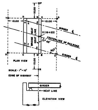
Figure 10-15 shows the plan for an askew
near-side abutment of a railroad bridge over a
highway. The outside line of the foundation is ABCD.
The neat line of the face of the abutment is MN. Set
stakes to define the direction of MN and ends AD and
BC. The stakes P, S, U, R, V, and T are offset from the
abutment so they will not be disturbed by foundation
excavating. The general procedure is as follows:
Figure 10-14.—Staking a right-angle abutment.
Figure 10-15.—Staking an askew abutment.
1. Take the dimensions for setting necessary stakes
from the abutment plans. Set the temporary point O at
the station location indicated.
2. With the instrument at O, sight along the center
line of the railroad, turn the skew angle (71°45´), set the
permanent stakes P and R, and set points M and N.
3. With the instrument at M, sight R, turn 90°, and
set permanent stakes S and T.
4. With the instrument at N, sight P, turn 90°, and
set permanent stakes U and V.
The face of the abutment is defined by P and R.
Stakes S, T, U, and V define the face of the end forms.
When construction begins, set stakes at A, B, C, and
D by measuring from the offset stakes. (These stakes
are knocked out as the excavation progresses.)
Concrete for the foundation is poured into the
excavation; if forms are needed for the foundation,
measure the distances from the reference offset stakes.
Set the elevations of the top and bottom of the
foundation from bench marks outside the excavation
area.
When the foundation has been poured to grade and
has had a day to set, mark temporary points on the top
at M and N by measuring 10 feet plus the distance AM
10-17


