Figure 8-31.-Commonly used map symbols.
making any attempt to interpolate or to draw the
complete contour lines. (See fig. 8-30, view B.)
Contour lines can be smoothly drawn freehand with
uniform width and with best results if a contour pen is
used. Breaks in the lines are provided to leave spaces
for the elevations. The numbers that represent these
elevations are written this way so that they maybe read
from one or two sides of the map. Some authorities
prefer that elevations also be written in a way that the
highest elevation numbers are arranged from the lowest
to the highest uphill. Spot elevations are shown at
important points, such as road intersections.
Figure 8-30, view C, shows the completed contour
map. For more refined work, the EA must trace the map,
using a contour pen on tracing paper or other appropriate
medium, to allow reproduction of more copies, if
needed.
Often on a large-scale map, you can represent the
true shape of features to scale. On small-scale maps,
however, you often use symbols for buildings and other
features. Center the symbol on the true position, but
draw it larger than the scale of the map. Detail of this
type is portrayed on the map by means of standardized
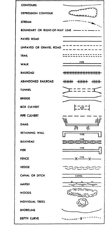
topographic symbols, such as shown in figure 8-31.
When you are plotting contours, remember that
stream and ridge lines have a primary influence on the
direction of the contour lines. Also, remember that the
slope of the terrain controls the spacing of the contour
lines. Contour lines crossing a stream follow the general
direction of the stream on both sides, then cross the
stream in a fairly sharp V that points upstream. Also,
remember that contour lines curve around the nose of
ridges in the form of a U pointing downhill and cross
ridge lines at approximate y right angles.
INTERPOLATING CONTOUR LINES
In the examples of interpolation previously given, a
single contour line was interpolated between two points
of known elevation, a known horizontal distance apart,
and by mathematical computation. In actual practice,
usual] y more than one line must be interpolated between
a pair of points; and large numbers of lines must be
interpolated between many pairs of points.
Mathematical computation for the location of each line
would be time-consuming and would be used only in a
situation where contour lines had to be located with an
unusually high degree of accuracy.
For most ordinary contour-line drawings, one of
several rapid methods of interpolation is used. In each
case it is assumed that the slope between the two points
of known elevation is uniform.
Figure 8-32 shows the use of an engineer’s scale to
interpolate the contours at 2-foot intervals between A
and B. The difference in elevation between A and B is
8-22