Figure 14-33.—Cut stake.
Figure 14-34.-Fillstake (not on centerline).
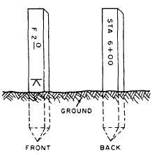
Figure 14-33 shows a cut stake that also
happens to be a center-line marker. Note that
station mark is written on the front of the stake
and the construction information on the back. On
grade stakes other than the center-line stakes, the
construction information should be written on the
front and the station marked on the back.
The stake shown in figure 14-34 indicates that
fill operations are to be performed. The letter F
at the top of the stake stands for fill. The numerals
24 indicate that 2 ft of fill are required to bring
the construction up to grade.
Some stakes indicate that no cutting or filling
is required. Figure 14-35, for example, shows a
grade stake that is on the proper grade and also
is a center-line stake. The word GRADE (or GRD)
is on the back of the stake, and the crowfoot mark
may not be indicated; some surveyors prefer to
use a crowfoot mark on all grade stakes. If this
Figure 14-35.-Stake on proper grade.
grade stake is not a center-line stake, the GRD
mark will be written on the front of the stake.
SETTING GRADE STAKES.— GRADE
STAKES are set at points having the same ground
and grade elevation. They are usually set after the
center line has been laid out and marked with hubs
and guard stakes. They can be reestablished if the
markers are disturbed. Elevations are usually
determined by an engineer’s level and level rod.
One procedure you can use for setting grade stakes
is as follows:
1. From BMs, turn levels on the center-line
hubs or on the ground next to a grade stake at
each station.
2. Reduce the notes to obtain hub-top or
ground elevation.
3. Obtain the finished grade elevation for each
station from the construction plans.
4. Compute the difference between finished
grade and the hub or ground elevation to
determine the cut or fill at each station.
5. Go back down the line and mark the cut
or fill on each grade stake or guard stake.
The elevations and the cuts or fills may be
recorded in the level notes, or they may be set
down on a construction sheet, as explained later
in this chapter.
Another procedure may be used that combines
the method listed above so that the computations
may be completed while at each station; then the
cut or fill can be marked on the stake immediately.
As before, levels are run from BMs; the pro-
cedure at each station is as follows:
1. Determine the ground elevation of the
station from the level notes to obtain HI.
2. Obtain the finished grade for the station
from the plans.
14-36