remarks side, the upper numbers with the
appropriate letter symbols (C for cut, F for fill)
are the cuts or fills; the lower numbers are the
distances out from the center. These values
indicate points at which the slope stakes are
driven. If a five-level or irregular section is being
recorded, the other points must be written between
those for the center and for the slope stakes.
These field notes given you the coordinates
that you can use to plot sections, as shown in
figure 14-30. In that figure for purposes of
clarity, only the lines at every 1/4-in. interval are
shown. The scale, both horizontal and vertical,
is 1 in. = 10 ft; therefore, the interval between
each pair of lines represents 2.5 ft.
The highway is to be 40 ft wide; therefore, the
edge of the pavement for each plotted section will
be 8 squares (8 x 2.5 = 20) on either side of the
center line. Figure 14-30 shows that, for station
305, the left-hand slope stake is located 29.8 ft
from the center line and 8.2 ft above grade. The
right-hand slope stake is located 35.3 ft from the
center line and 12.3 ft above grade. Note how the
locations of these stakes can be plotted after you
have selected an appropriate horizontal line for
the grade line and how the side slopes can then
be drawn.
The ground line at the center line is 9.3 feet
above grade. Plot a point here, and then finish
the plot of the section by drawing lines from the
center-line point to the two slope stake points.
Plot a five-level section in exactly the same
way, except that you plot in additional ground
points between the center line and the slope stakes.
Layout/Stakeout Procedures
The design-data survey is followed by the
construction survey that consists broadly of the
LAYOUT or STAKEOUT survey and the AS-
BUILT survey, which will be discussed later in
this chapter. In a layout survey, both horizontal
and vertical control points are located and marked
(that is, staked out) to guide the construction
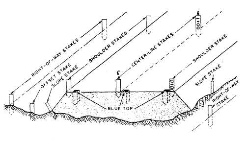
crews. Figure 14-31 identifies various stakes and
hubs used in highway or road construction and
their typical arrangement. The functions of the
various stakes and hubs are described briefly as
follows:
1. CENTER-LINE STAKES indicate the
exact center of the roadway construction.
2. SHOULDER STAKES are used to indicate
the inside edge of the roadway shoulders. These
stakes are set opposite each center-line stake.
3. REFERENCE HUBS, as the name implies,
are used to reference other stakes or to aid in
establishing or reestablishing other stakes.
4. SLOPE STAKES mark the intersection of
side slopes with the natural ground surface. They
indicate the earthwork limits on each side of the
center line.
5. RIGHT-OF-WAY STAKES indicate the
legal right of passage and outmost bounds of
construction.
6. GRADE STAKES indicate required grade
elevations to the construction crews. During the
final grading stage of construction, hubs called
“blue tops” are used in lieu of stakes. The blue
Figure 14-31 .-Typical arrangement of various hubs and stakes on a road section (final grading).
14-34