Figure 10-15.-Dimensioning concrete-masonry construc-
tion; window and door openings.
outside face of the studs to the center line of the
partition (fig. 10-14, view B). In some cases,
partitions are measured from the outside face of
the studs to the face of the interior stud
walls. The important thing is to be consistent.
You must take extra care to see that all
of the partition measurements are referenced
from the same exterior wall. In wood frame
with veneer construction, dimensioning is the
same as wood frame without veneer (fig. 10-14,
view C). The only difference is in the overall
dimension showing the total size of the house
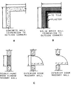
when the veneer is added. In concrete-masonry
constructions, the dimensions are all given
to the face of the walls and not to the
center lines, as shown in figure 10-15, views A
and B.
2. In wood frame construction, doors
and windows are dimensioned to their center
lines. This is not the case in concrete or
masonry construction, as shown in figure
10-13. Notice in this figure that the rough
openings of the doors and windows and the
distance between the rough openings are dimen-
sioned. This is the correct procedure for
concrete or masonry construction. Also see
figure 10-15, view C, for dimensioning doors and
windows in masonry construction.
3. Throughout your dimensioning of the floor
plan, and then again when finished, take time to
check your dimensions for legibility and accuracy.
Make sure, also, that the cumulative total of all
short dimensions add up to their corresponding
overall dimension.
Elevations
ELEVATIONS are orthographic projections
showing the finished interior and exterior
appearance of the structure. Interior elevations
are required for important features, such as
built-in cabinets and shelves, but it is not
uncommon for elevations to be drawn for all
interior walls in each room of a building.
Cabinet elevations show the cabinet lengths
and heights, distance between base cabinets
and wall cabinets, shelf arrangements, doors
and direction of door swings, and materials
used. Interior wall elevations show wall lengths,
finished floor-to-ceiling heights, doors, windows,
other openings, and types of finish materials
used.
Exterior elevations show the types of materials
used on the exterior, where the materials
are used, the finished grade around the struc-
ture, the roof slope, the basement or foundation
walls, footings, and all of the vertical dimen-
sions.
Basically, four elevations are needed in a set
of drawings to complete the exterior description:
the front, the rear, and two sides of a structure,
as they would appear projected on vertical
planes. A typical elevation is drawn at the same
scale as the floor plan, either 1/4 in. = 1 ft or
1/8 in. = 1 ft, but occasionally a smaller scale may
be used because of space limitations, or a larger
scale, to show more detail.
There are several methods used to identify
each elevation as it relates to the floor plan. The
method most commonly used by SEABEEs is to
label the elevations with the same terminology
used in multi-view and orthographic projection;
that is, FRONT, REAR, RIGHT-SIDE, and
LEFT-SIDE ELEVATIONS (fig. 10-16). On
10-18