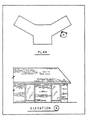
Figure 10-17.-Use of a letter to identify elevation on
irregular floor plans.
irregular plans, such as shown in figure 10-17, the
elevations may be identified by a letter or a
number.
The following basic procedures will serve as
a guide in the development and drawing of
elevations:
1. Use the same sheet size as that of the floor
plan. Determine the overall height and length of
the elevation from the floor plan and wall
section (predetermined by prior computation or
a sketch). We assume that you are using the same
scale for elevations as for the floor plan. Block
in the views with construction lines placed in a
logical order, such as starting with the front view
and working around the building. Generally, the
front and right-side elevations are next to each
other, and the rear (if necessary) and the left-side
elevations are shown below. Whenever possible,
show all of the elevations on one sheet.
2. Draw the exterior limits of the elevations.
The floor plan may be placed underneath the
drafting sheet on which the elevations will be
drawn. Vertical projections determine and define
the length of exterior walls, any breaks or
corners along the wall, windows, roof overhang,
doors, and other elements, such as chimney
location. Horizontal projections from a wall
section locate the height of the doors and
windows, the cave line, the bottom of fascia, the
top and bottom of the footing, and the top of the
roof to the space in which the elevation is to be
drawn.
3. Repeat this process until all of the
elevations are lightly laid out and final changes
are incorporated into the exterior design. Darken
the drawing, following the same procedures
used in the floor plan: from left to right, top to
bottom, until completed. You must remember
that all of the portions drawn below the grade line
are shown with a dark hidden line, and the grade
line is the darkest line on the elevation drawing
(disregarding the border lines).
4. Add the dimensions. Show only vertical
dimensions to include the following: the bottom
of the footing, all of the finished floor lines,
finished ceiling lines, finished grade, height of
features, chimney height, and freestanding walls.
Refer to chapter 3 of this book for additional
information on drafting format, conventions, and
techniques.
5. Add all notes and pertinent information on
exterior materials and finishes, title, scale,
window identification marks, and roof pitch.
Section symbols (fig. 10-6) may be shown on the
elevation to indicate where the sections have been
taken (fig. 10-16).
6. Finish up the elevations by adding the
material symbols (fig. 10-7). Notice that symbols
do not take the place of the material notations;
they just supplement them. Go over your eleva-
tion checklist for completeness and accuracy of
information.
STRUCTURAL DRAWINGS
STRUCTURAL DRAWINGS (sometimes
identified with the designating letter S on their title
blocks) consist of all the drawings that describe
the structural members of the building and their
relationship to each other. A set of structural
drawings includes foundation plans and details,
framing plans and details, wall sections, column
and beam details, and other plans, sections,
details, and schedules necessary to describe the
structural components of the building or struc-
ture. The general notes in the structural drawings
should also include, when applicable, roof, floor,
wind, seismic, and other loads, allowable soil
pressure or pile bearing capacity, and allowable
stresses of all material used in the design.
10-20